- 您现在的位置:买卖IC网 > Sheet目录321 > DM164120-1 (Microchip Technology)BOARD DEMO PICKIT 2 LP COUNT
�� �
�
 �
�LPC� Demo� Board� Lessons�
�3.2.10�
�Lesson� 10:� Interrupts�
�New Instructions�
�RETFIE�
�SWAPF�
�Return� from� Interrupt�
�Swap� nibbles� in� file� register�
�Interrupt� Sources�
�Most� of� the� peripherals� can� generate� an� interrupt;� also� some� of� the� I/O� pins� may� be�
�configured� to� generate� an� interrupt� when� they� change� state.�
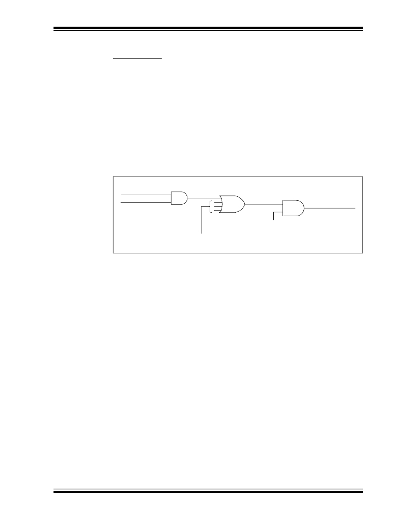
�When� a� peripheral� needs� service,� it� sets� its� interrupt� flag.� Each� interrupt� flag� is� ANDed�
�with� its� enable� bit� and� then� these� are� ORed� together� to� form� a� Master� Interrupt.� This�
�master� interrupt� is� ANDed� with� the� Global� Interrupt� Enable� (GIE).� See� the� Interrupt�
�Logic� Figure� in� the� PIC16F685/687/689/690� Data� Sheet� (DS41262)� for� a� complete�
�drawing� of� the� interrupt� logic.� The� enable� bits� allow� the� PICmicro� to� limit� the� interrupt�
�sources� to� certain� peripherals.�
�FIGURE� 3-9:�
�Interrupt� Flag�
�Interrupt Enable�
�INTERRUPT� LOGIC� SIMPLIFIED�
�Master Interrupt�
�Global� Interrupt� Enable�
�Other� Interrupt� Sources�
�When� the� master� interrupt� line� is� asserted,� the� PICmicro� finishes� the� current�
�instruction,� stores� the� next� address� on� the� CALL� stack� then� jumps� to� the� Interrupt�
�Service� Routine� (ISR).� It� also� clears� the� GIE� bit,� preventing� another� interrupt� from�
�occurring� while� servicing� the� current� one.�
�Save� Current� Context�
�The� first� thing� the� ISR� must� do� is� to� save� the� current� context� of� the� processor� so� it� can�
�be� restored� before� returning� to� the� main� program.� Any� SFR� that� may� be� changed� in� the�
�ISR� must� be� saved,� which� means� the� Wreg� and� Status� registers� at� the� very� least.� The�
�last� 16� bytes� of� each� PIC16F690� file� register� page� are� unbanked� and� are� good� places�
�to� save� the� context,� as� they� may� be� accessed� from� any� register� page� without� regard� to�
�the� RP0� and� RP1� bits� in� the� Status� register.� The� location� of� unbanked� registers� may�
�vary� from� part� to� part.� Check� the� register� map� to� find� the� unbanked� region� for� a� specific�
�part.�
�Identify� Triggering� Event�
�Next,� the� ISR� has� to� figure� out� what� triggered� the� interrupt.� It� has� to� check� the� interrupt�
�flags� to� determine� what� caused� the� interrupt.� When� it� finds� the� source,� then� it� can�
�service� the� peripheral.�
�?� 2005� Microchip� Technology� Inc.�
�DS51556A-page� 29�
�发布紧急采购,3分钟左右您将得到回复。
相关PDF资料
DM164120-3
BOARD DEMO PICKIT2 28-PIN
DM164120-5
BOARD DEMO PICKIT 2 64/80-PIN
DM164123
KIT MANAGEMENT SYSTEM PICDEM
DM180021
KIT STARTER MPLAB FOR PIC18F MCU
DM183022
BOARD DEMO PIC18FXX22 64/80TQFP
DM183032
BOARD EXPLORER PICDEM PIC18
DM240001
BOARD DEMO PIC24/DSPIC33/PIC32
DM240002
BOARD DEV EXPLORER 16 44-PIN
相关代理商/技术参数
DM164120-1
制造商:Microchip Technology Inc 功能描述:DEVELOPMENT TOOLS - PICKIT 2 LOW PIN COU
DM164120-2
功能描述:开发板和工具包 - PIC / DSPIC PICkit 2 44-Pin Count Demo Brd RoHS:否 制造商:Microchip Technology 产品:Starter Kits 工具用于评估:chipKIT 核心:Uno32 接口类型: 工作电源电压:
DM164120-3
功能描述:开发板和工具包 - PIC / DSPIC PICkit 2 Count Demo Board RoHS:否 制造商:Microchip Technology 产品:Starter Kits 工具用于评估:chipKIT 核心:Uno32 接口类型: 工作电源电压:
DM164120-4
功能描述:开发板和工具包 - PIC / DSPIC PICkit 2 1 Dem Board RoHS:否 制造商:Microchip Technology 产品:Starter Kits 工具用于评估:chipKIT 核心:Uno32 接口类型: 工作电源电压:
DM164120-4
制造商:Microchip Technology Inc 功能描述:PICkit 2 18-Pin Demo Board
DM164120-4/16F1827/PG164130
制造商:Microchip Technology Inc 功能描述:PICKIT PIC16F648A DEMO BOARD 制造商:Microchip Technology Inc 功能描述:KIT STARTER 18PIN F1 ENHANCED CORE 制造商:Microchip Technology Inc 功能描述:PICKIT, PIC16F648A, DEMO BOARD 制造商:Microchip Technology Inc 功能描述:PICKIT, PIC16F648A, 18 PIN, DEMO BOARD; Silicon Manufacturer:Microchip; Core Architecture:PIC; Core Sub-Architecture:PIC16; Silicon Core Number:PIC16F; Silicon Family Name:PIC16F18xx; Kit Contents:Demo Board, 2x Bare PCB Boards
DM164120-5
功能描述:开发板和工具包 - PIC / DSPIC PICkit 2 64 demoBoard RoHS:否 制造商:Microchip Technology 产品:Starter Kits 工具用于评估:chipKIT 核心:Uno32 接口类型: 工作电源电压:
DM164123
功能描述:开发板和工具包 - PIC / DSPIC PICDEM Sys Mgmt Board RoHS:否 制造商:Microchip Technology 产品:Starter Kits 工具用于评估:chipKIT 核心:Uno32 接口类型: 工作电源电压: